


Better Engineering Through
Multibody Dynamic Simulation
August 2019 | Issue #21
In This Issue:
• A Closer Look: RecurDyn V9R2 User Interface Enhancements
• Expert Viewpoint: Why should we plan to do more simulation?
• 2019 MotionPort Users Conference Update
• User Tip: How to use the 2D Belt
• User Tip: Differences between hyperelastic material models
A Closer Look
RecurDyn V9R2 User Interface Enhancements
Let’s briefly review the following new RecurDyn functionality:
• System Navigator – quickly identify structures of subsystems and immediately move to the desired subsystem regardless of hierarchical order
• CAD Import Enhancements – intuitively identify CAD hierarchical structures and effectively import original CAD structures
• General Grouping – group any combination of desired entities together
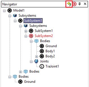
System Navigator
In the RecurDyn modeling process the hierarchical structure can be complicated if using multiple subsystems, such as models with several belts, chains, track assemblies, or user-defined subsystems. The System Navigator allows users to select an entity directly (whether it is a Marker, Joint, Force, Contact, Expression, Parametric Point, Parametric Value, Subsystem, Group, or Clone body) that belong to a specific Subsystem, instead of first entering the Edit mode of the Subsystem. In addition, regardless of hierarchical order, you can enter Edit Mode of the desired Subsystem or Body immediately, enabling quicker subsystem modeling.
As shown to the right, the System Navigator, which has the same form as the database window, displays multiple Subsystems and their associated Bodies, Joints, and Forces within a tree menu.
The ‘Move to the Subsystem’ function places the model into the Edit mode of the selected Subsystem or Body with one click. To use, right-click on the name of the Subsystem or Body to enter Edit Mode (shortcut key: I).
Click play below to watch a video on how the new System Navigator functions.
CAD Import Enhancements
The ‘Import CAD’ function in RecurDyn V9R2 has been enhanced to automatically create each Body and Subsystem by merging multiple geometries based on the hierarchical structure of the original CAD file. The user can control this process through an intuitive user interface. The major benefits are:
- The user does not have to group all of the individual solids manually, and
- The user can efficiently select solids or subassembly geometry to be omitted during the import.
This allows the user to take advantage of the organizational structures of the original CAD file and reduces the time needed to import and process CAD geometry.
When importing CAD files, it is now possible to effectively import the hierarchical structure from CAD into RecurDyn by using ‘CAD Import Options’ as shown below. The Hierarchy Conversion Level allows users to select the target of the CAD hierarchical structure to be a Body or Subsystem when importing geometry from a CAD file into RecurDyn.
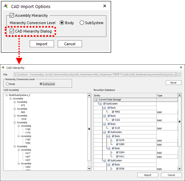
The CAD Hierarchy dialog box allows the user to editing the hierarchical structure of the CAD file in detail, specifically omitting and merging of the CAD solids to be imported.
The CAD Import Options dialog can be enabled or disabled by toggling the option, ‘CAD Import Options Dialog when Importing CAD Files’ that is located in the Home tab, Setting group, and the CAD command.
General Grouping
It is now possible for users to group and manage a set of desired entities in order to improve the efficiency of working with a complex RecurDyn model.
It is especially convenient to be able to perform ‘Object Control’ (move), changing layers, and changing rendering types of the entities in the Group at the same time.
In the Group Properties dialog box, it is also possible to display the Properties dialog box of an individual entity (or entities). It allows users to manage modeling entities more efficiently because it is easier to select and edit desired entities when they are grouped into logical subsets.
Click play below to watch a video highlighting the use of general grouping.
Expert Viewpoint
Why Should We Plan To Do More Simulation?

From time to time we encounter profound information from a simulation expert that is worthy to share with you.
On Thursday, July 11, 2019, Dr. Keith Meintjes, who is a Fellow and an Executive Consultant in Simulation and Analysis with CIMdata, gave a webinar, “The Rise of Simulation – Redux.”
In that presentation he had a slide with three questions and two sets of answers. The first set of answers contained the general perception or “conventional wisdom” that has traditionally communicated. The second set of answers contained Dr. Meintjes’ correct answer according to his many years of experience.
Here are the questions and answers:
1. What is the purpose of “Just in Time”?
● General Perception: To reduce the cost of in-process inventory
● Correct Answer: To stress the system to reveal weaknesses
2. Why should we define Standard Work?
● General Perception: To enable the work to be done by less-skilled people
● Correct Answer: To enable continuous improvement
3. Why should we plan to do more simulation?
● General Perception: To reduce the cost of physical testing
● Correct Answer: To enable more, and earlier, learning cycles
Was your response like ours? We first disagreed with the “correct answers” but after some thought we came around to agree with his perspective.
Regarding simulation, we hope that our clients are successful in using RecurDyn, Particleworks, EDEM, and MBD for ANSYS to enable more, and earlier, learning cycles. Please contact us if you would like us to help you with this goal.
By the way, for more information about Dr. Meintjes, please go to: https://www.cimdata.com/en/about-cimdata/leadership-team, and search on Meintjes (there are bios for a lot of people on this page!).
To view the slides of Dr. Meintjes webinar presentation go to: https://www.cimdata.com/images//Webinars/CIMdata_Webinar_Rise_of_Simulation_11July2019.pdf
To view the webinar go to: https://register.gotowebinar.com/register/517012756400019725.
RecurDyn News & Tips
User Tip:
Flat & Timing Belt
The belt segments types that are useful for the 2D Belt system are the Flat Belt and Timing Belt. The 2D Belt simulation does not consider motion in the depth direction. Therefore it is not meaningful to use V-Belt and Ribbed V-Belt types because the side contact that is critical to their behavior is not considered. For this reason the V-Belt & Ribbed V-Belt are not supported in the 2D belt system.
Guide Bodies
In the past the belt system could not use a Guide body (sliding contact), instead only rollers could be used to guide the belt. However, conveyor systems or even the handrail on an escalator features belts that are guided by sliding contact. Therefore linear and arc guide bodies were added to RecurDyn to provide the needed sliding contact.
When working with the guides it is important to set the contact normal to point towards the belt, which is controlled using the Up/Down buttons on the linear guide and by changing the sign of the radius value on the arc guides.
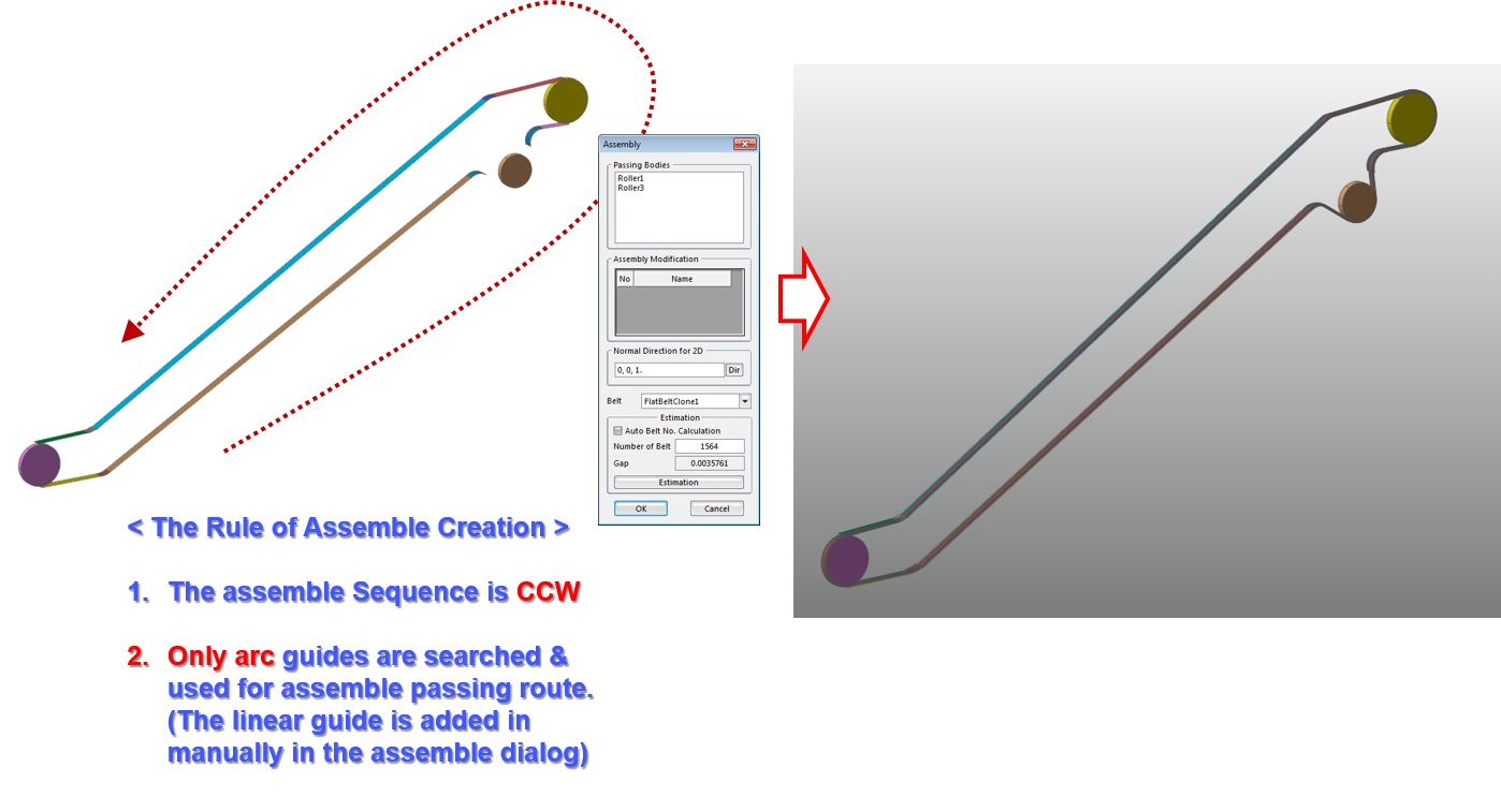
2D Belt – Assembly
The 2D Belt is always assembled within an X-Y plane. Directions for the 2D belt assembly are included in the images below.
For additional information on using the 2D Belt, please refer to a full-length article on our website.
If a belt assembly in your product undergoes primarily 2D behavior, there is a faster way to simulate it using the 2D belt option of the RecurDyn/Belt toolkit.
Another benefit of this option is that long belts with thousands of segments can be solved efficiently. The commands of the 2D Belt are found within the 2D Belt group of the Belt tab.
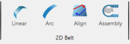
How to use the 2D Belt
User Tip:
What are the differences between the various hyperelastic material models?
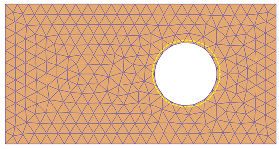
In RecurDyn, how do you select the nodes as shown below?
Likewise, the ‘Select by Polygon’ option enables you to define the selection area as a polygon with any number of sides by clicking on the corner points and then clicking on the right mouse button to close the area.
These select methods can be used for flexible body entities such as nodes and elements, as well as rigid bodies, joints or forces.

Another tip!
Please note that in the same toolbar there are buttons to filter the type of entity that is included in the selection.
The top button is the All option, and all types of entities are selected.
The other buttons are, respectively: Body, Group, Marker, Joint, Force, Contact, Parametric Point, and Subsystem. When any of these other selection modes are active, only the specified entity type can be selected
User Tip:
How can I define contact to both sides of a flexible body that consists of shell elements?
RecurDyn uses ‘Patch Sets’ to define contacts with flexible body elements.
Consider the model below that consists of 2 bodies, named RigidBody and FFlexShellBody. The left edge of the flexible body is fixed, and the rigid body moves up and down. Consequently the cylinders in the rigid body make contact with the flexible body.
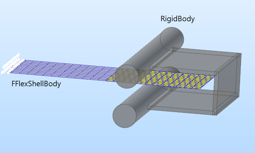
To define the two needed contacts, create 2 contact entities between SetPatch1 (shown in yellow) of FFlexShellBody and the RigidBody.Unite solid geometry.
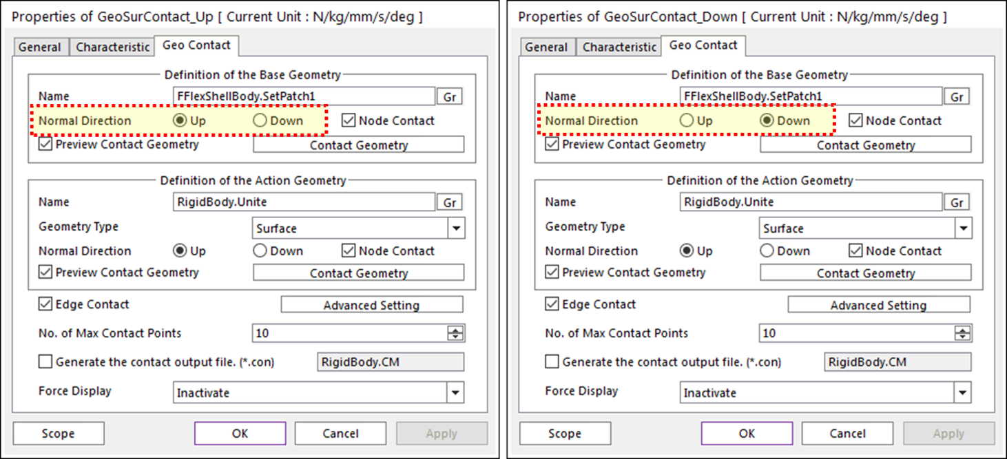
When defining contacts to both sides of a mesh defined with shell elements you need two contacts, but the User Tip is that you can use the same patch set for both contacts. This is done by setting the normal direction of SetPatch1 of the first contact to UP, and the normal direction of SetPatch1 of the second contact to DOWN, as shown in the dialog boxes below. This simple method enables both sides of the flexible body to contact with the rigid body while only requiring the definition of a single patch set.
For the full details, the example RecurDyn model, and for an animation of the working contacts please refer to the full article by clicking here.

Please note date change!
Wednesday, September 25th and Thursday, September 26th.
This event is FREE* to attend, register early to reserve your spot.
Want to learn more about how MotionPort can help you with your projects? Contact us today to schedule a free web meeting to learn how RecurDyn, Particleworks, and MBD for ANSYS are helping our clients and how they can help you.
MotionPort LLC | St. George, UT | www.motionport.com
Click here to unsubscribe