


Better Engineering Through
Multibody Dynamic Simulation
May 2019 | Issue #18
In This Issue:
• Announcing 2019 RecurDyn Users Conference
• User Tip: Comparing RecurDyn models using *.rmd files
• User Tip: How to define a motion control that can be turned off during the simulation

Announcing the 2019
RecurDyn Users Conference
In our January newsletter we asked for feedback regarding two options for this year’s RecurDyn Users Conference – in-person or streaming. We received positive responses for both but there wasn’t a critical mass for the traditional in-person conference. Since we are engineers, we have developed a solution!
MotionPort is pleased to announce that with the 2019 conference we will let you “have it your way,” and it will be held both as an on-site conference at our headquarters in St. George, UT as well as a live streaming event. You can choose the option that works best for you!
At this year’s conference you will learn about RecurDyn V9R3 (to be released at the end of the summer), participate in hands-on learning, and interact with other users to gain insights. Please note that the schedule for Thursday will be 8:30 am – 4:30 pm MST and the schedule for Friday will be 8:30 am – 3:00 pm MST. An agenda will be provided by mid-August to those who register.
This event is FREE* to attend, register early to reserve your spot.
We will organize a local outdoors event on the next day (Saturday) if we have enough participants come to St. George. This area is full of outdoor activities that are sure to invigorate you – from hiking in Zion National Park to cruising through the desert landscape with an ATV. Let us know if you are interested when you register!
RecurDyn News & Tips
User Tip:
Comparing RecurDyn models using *.rmd files
The search for a better mechanical design of an assembly in motion commonly requires the study of multiple versions of a mechanical model. While the basic model topology (number of bodies, joints, and forces) stays the same, there are adjustments of various model parameters in an attempt to tune the model. However, when the new results are undesirable, you may want to revert back to an earlier configuration. But what if you are not sure which parameters you modified? Even if the results are desirable, you may not know the sequence of parameter modification given the various combinations that you tried over different runs.
If there is a back-up for each of the original files, you can open each RecurDyn model file in the RecurDyn user interface to identify the parameter values. This approach can be time consuming. A faster approach to identify changes is to compare *.rmd text files for the various simulations. An *.rmd file, by default, is always created for each RecurDyn simulation and it contains the model definition that is used by the RecurDyn solver. An *.rmd file is located with the other result files for each run, including the animation and plot files (*.rad or *.rplt file extensions).
For example, let’s consider identifying the differences between two variations of an engine valve train model, ValveTrain1 and ValveTrain2 (Click here to download 2 sets of example RecurDyn model and *.rmd files). Both models are small, consisting of 4 bodies, 5 joints, 1 spring, and 1 contact.
While it is not easy to compare the two text files manually, various computer utilities are available to automate this task. You probably have access to Microsoft Word, and it has the ability to compare documents, but the output may not be as clear as with other tools (Click here to find out how to use Word 2016 to compare two documents).
You can download WinMerge for free at http://winmerge.org/ (it is open-source software).

- Install WinMerge on your computer first.
- After running WinMerge, on the File menu, click Open and select
the two different *.rmd files.
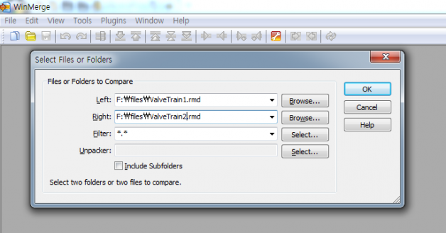
WinMerge provides a direct comparison between the two .rmd files.
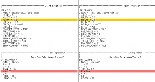
In WinMerge, you can verify the differences between these two text files by going through them with the arrow button in the toolbar. The highlighted lines indicate the differences between the two text files.
The differences between ValveTrain1 and ValveTrain2 are:
- Revolute2 dynamic coefficient of friction: 0.5 / 0.8
- Spring1 spring coefficient: 100 / 200
There is no published documentation for the *.rmd file format. However, in the case of MU_DYN, you can easily determine that the compared parameters belong to joint Revolute2 by the ‘NAME = ‘Revolute2.JointFriction’ line. Even if you don’t know exactly what the parameters in the *.rmd file mean, check the dialog box for Revolute2 properties and you will recognize that the dynamic coefficient of friction is the parameter of interest.
User Tip:
How to make a body that is constrained by a joint perform a free motion
Sometimes we want to load up a spring and then release it in order to obtain a dynamic condition of interest. This article explains how to use two different methods to stretch out a linear spring under the control of a translational joint, and then release the sliding motion. Both methods utilize an expression, and the motion release can be functions of time, motions, forces or sensors. Note that the approaches can, with a few adjustments, also be applied with rotational springs.
The RecurDyn motion entity defines a specific motion input as a function of time (best practice), whether the motion is a displacement, velocity, or acceleration. However the motion entity is not able to release its motion control. Therefore, to accomplish the release you need to create an extra “dummy” body with a corresponding joint and force. You will define the dummy body along the kinematic chain leading to the body with the motion of interest.
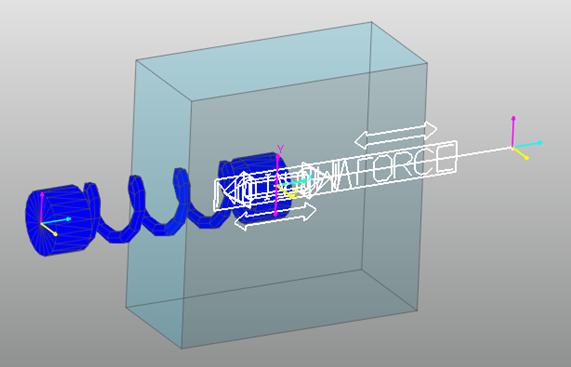
Let’s use the following example to learn how to create such a simulation model. In the figure, a translational joint connects a target body (box geometry) to ground. A spring force is defined between the same two bodies. A motion moves the target body to the right for 0.5 seconds at a constant velocity, stretching the spring.
The desired behavior is that after 0.5 seconds the motion is released and the target body is free to move to the left due to the force of the stretched spring.
The follow steps are needed for both techniques:
1. Create a target body (box geometry) as shown in the figure.
2. Create a dummy body (sphere geometry) with negligible weight near to the center of the target body.
3. Add a simple spring between ground and the target body.
4. Create two translational joints with a horizontal orientation, the first from the ground to target body and the second from the ground to the dummy body. Add a motion to the second joint to move the dummy body to the right at 10 length units per second.
5. Create an axial force between the target body and the dummy body to fix them together with a strong spring force as if they were one body. The magnitude of the spring force is defined in an expression, where the force is a function of the displacement between the target and the dummy bodies and a high spring coefficient.
At this point the first method would be to add an IF function to the expression to change the magnitude of the spring force to “0” after 0.5 seconds, as shown below.
IF(TIME-0.5: 100000 * ( DX(target body marker, dummy body
marker) ), 0, 0)
The second method is to use the Scenario analysis option to deactivate the connecting axial force after 0.5 seconds of the simulation. You can refer to the “Analysis, Scenario, Step to create a Scenario File, Deactivate Command” of the RecurDyn help documentation for information about setting this up.
With both methods the force connection between the target body and the dummy body is broken completely at 0.5 seconds. This also breaks the indirect horizontal connection between the target body and the ground. The target body can now freely translate along the first translational joint, and will be pulled to the left by the stretched spring.
You can simulate more sophisticated motions by applying these methods with different joint types and connecting conditions.
Want to learn more about how MotionPort can help you with your projects? Contact us today to schedule a free web meeting to learn how RecurDyn, Particleworks, and MBD for ANSYS are helping our clients and how they can help you.
MotionPort LLC | St. George, UT | www.motionport.com
Click here to unsubscribe