All Posts By

Evan Daniel

Improving a Coffee Capsule Packaging Machine Using RecurDyn Multibody Simulation

Improving a Coffee Capsule Packaging Machine Using RecurDyn Multibody Simulation

Analysis Goal: Increase the production capacity by 25% without increasing overall costs and energy consumption.

Production capacity is one of the most important features of an automatic packaging machine. OPEM’s designers, in Parma, Italy, are constantly looking for new design solutions with increased capacity and reliability, attractive pricing, and small dimensions that will enhance their competitiveness. The main objective of this project was to increase the packaging capacity by 25% without affecting the general architecture, the size of parts and the energy efficiency of the machine. The objectives were achieved by optimizing the motion profiles of all of the actuators (cams and controlled electric drivers) because optimizing motion profiles is the way to achieve higher capacity without increasing the power demand and dynamic loads. At the same time the behavior of a complex chain mechanism had to be considered. A large number of RecurDyn multibody dynamics simulations were performed in order to check and verify the effects of the optimized motion profiles on the overall system behavior.

Espresso

Development Process

  1. Motion profiles are applied to all ideal motors equipping the machine. Motion profiles are designed and optimized to guarantee continuity and lowest possible accelerations, while achieving the desired displacements at the desired instants.
  2. The rigid multi-body model of the entire machine verifies that the motion profiles are properly synchronized. The same model also measures the power requirements, which determines the selection of the proper motors. Rigid multibody simulation is the best approach to verify motion profiles because each simulation runs quickly. Running multiple iterations to optimize the profiles is easy and can be done automatically. The RecurDyn Chain Toolkit allows for the easy modeling of the chain mechanism and the large number of contacts can be calculated quickly.
  3. This model includes a FullFlex representation of the thin film that is used to seal the capsules. Flexible multi-body (reduced ex and full ex) is necessary to check the effectiveness of the proposed design solutions. Although some components of the machine are largely flexible, the relative positioning of the capsule, film and tools must also be guaranteed in severe dynamic conditions.
  4. The multi-flexible body model of the entire machine is used to verify that the positions of tools and capsules are guaranteed even when the structures deform in dynamic conditions.
  5. This model also calculates the dynamic reaction forces at the constraints that connect each machine sub-system to the main frame.
  6. The loads obtained from the multi flexible body model are used for structural assessment (strength and fatigue) using finite element analysis software.
Cut and Weld
Film Feeder Flex
Cut Weld Flex
Structure

Gear Contacts in RecurDyn/DriveTrain, Including the Gear Meta Model

Basics of Modal Flexible Body Simulation

Review of RecurDyn/DriveTrain

RecurDyn/DriveTrain defines and simulates drivetrain components, including gears, bearings, and shafts (see toolkit icons in the figure). Users can easily simulate and analyze drivetrain systems with specialized user interfaces, a specialized solver, and dedicated post-processing.

The GearKS and BearingKS toolkits have been developed through a technical partnership with Gleason’s KISSsoft, and offers KISSsoft’s Gear Analytic Contact and tens of thousands of gear and bearing libraries. This allows RecurDyn users to accurately calculate a variety of results including transmission error for noise and vibration evaluation.

Gear Contact elements in RecurDyn/DriveTrain

In the GearKS toolkit the contact between gears is referred to as a gear force. GearKS supports 3 gear force types as shown in the image below: Inactivate, KISSsoft Force, and KISSsoft Force (Meta Model). These contacts are explained below, with a focus on the meta model option, because it is expected to be used frequently.

KISSsoft Force

Gear Force Types

Inactivate – If this type is selected, GearKS doesn’t calculate the gear contact. Instead, other contacts such as a gear involute contact or a geo contact must be defined. To use gear involute contact, first set the Gear Force Type to Inactivate and then create the gear involute contact using the RecurDyn/Gear Toolkit (different than the GearKS toolkit).

KISSsoft Force – The gear contact is calculated by the co-simulation between RecurDyn and the embedded KISSsoft solver. Each time step, RecurDyn transfers the updated position of the gears to KISSsoft and the KISSsoft solver embedded in RecurDyn calculates the gear contact. The reaction force/torque is transferred from KISSsoft to RecurDyn.

KISSsoft Force (Meta Model) – This method is generally recommended because it is very fast and has high accuracy. Unlike the KISSsoft Force (Direct Co-Simulation) option, KISSsoft Force (Meta Model) uses the pre-calculated Gear Meta Model in the simulation, which is the reason for its speed. The Gear Meta Model (*.gmm file) must be created using up to 6 parameters which are related to the location/ orientation of the gear pair before simulation. The generation of the Gear Meta Model requires from several minutes to several hours. The Gear Meta Model is reusable if the same gear pair is used for another model. The same Gear Meta Model can be used for the several gear pairs in the same model.

More About the Gear Meta Model

In general, meta models are also known as surrogate models, or approximate models. A meta model is prepared by running a series of analyses with varied values for some number of gear-related variables. The outputs of all of these analysis runs are used to construct an N-dimensional response surface that quickly predicts the outputs of interest as a function of a specific input case. Using the response surface, you can quickly obtain gear contact results that accurately consider transmission errors because the surface is generated from accurate KISSsoft gear contact data. The gear meta model is generated with a set of static analyses and the meta model data is stored in a *.gmm file.

The 6 gear variables that may be considered include Rotational Angle (most important), Penetration, Distance Error, Axial Offset, Twist, and Tilt. These variables are described in the figure below.

The default setting uses only 2 parameters: Rotational Angle and Penetration. The accurate simulation of gear vibrations requires an accurate calculation of the change in meshing stiffness. The meshing stiffness of a gear varies with several factors, and rotation is the most important variable for high-accuracy gear contact.

If the gears are constrained by revolute joints, the Distance Error, Twist, and Tilt parameters can be ignored. The Axial Offset can be ignored in many cases. Nonetheless, for the most accurate result, it is recommended to use all 6 parameters. The time to generate a Gear Meta Model (varies depending on the system) is as low as several minutes when 2 parameters are used but may require several hours when all 6 parameters are used.

Choosing the Right Contact Type for Your Model

Please refer to the table.

The KISSsoft Force (Meta Model) is recommended in most cases because of its high accuracy and speed. Even though it takes time to generate Gear Meta Model, Gear Meta Model is reusable. Another reason to use KISSsoft Force (Meta Model) is if the gear specification is already fixed.

While the KISSsoft Force (Direct) is a little more accurate, the benefit of faster simulation speed (>50x) with the KISSsoft Force (Meta Model) compensates for the slight loss of the accuracy. If you only need to run 1 or 2 simulations then the KISSsoft Force (Direct) option can be a good choice.

The Gear Involute Contact is a good choice if the focus of the model is on macro system behavior rather than the micro effects such as the transmission error or the effect of the micro geometry of the gear. Gear Involute Contact is very convenient because no pre-calculation is needed.

If you need to simulate a flexible gear then you should use the Geo Surface Contact because the KISSsoft Force and Gear Involute contacts don’t support flexible bodies.

Calculation of Mass Properties When merging bodies with different materials

When you merge rigid bodies using the Merge Body command, the mass properties of the merged body are automatically calculated and applied, using one of two methods. The first method described below is used when the “User Input in Material Input” option (highlighted in the figure) is not checked and the second method is used when this option is checked.

First Option: Use the physical properties of the target body

The mass properties of the merged body are based on the total solid volume and assuming the material type of the Target Body.

For example, let’s assume that the Target Body is Steel and that Body B (Aluminum) is merged into it. The newly merged body has a material type of steel and the mass properties are calculated on the total solid volume. On the other hand, if body B were the target body, the material type of the resulting body would be aluminum. Given this behavior, this option is only appropriate when merging bodies of the same material.

Second Option: User Input in Material Input

After calculating the mass and moment of inertia from each of the Source Bodies, combine their mass properties with the mass properties of the target body. Set the mass properties of the target body with these combined properties, using the Material Type mode of “User Input” in the body properties. In summary, use this option when merging bodies with different material types in order to obtain accurate mass properties for the combined body.

Basics of Modal Flexible Body Simulation

Basics of Modal Flexible Body Simulation

This article is intended to help beginners understand a principle that is included in RecurDyn, in this case the modal approximation to flexibility in the RFlex (‘Reduced Flexibility’) module. You can use this information to help others understand the work that you do. There are also some usage tips that might be useful to you.

Including the flexibility of a body can be important. For example, a person designing a ruler must determine the difficulty of bending the ruler as well as the difficulty of breaking the ruler.

For another example, consider a bridge. A truck driver could be concerned if heavy shaking occurs when his/her truck goes over the bridge. Since the bridge didn’t collapse even when a heavy truck went across, does that mean the design is acceptable?

No, it does not.

An engineer must consider how much of a load a bridge can handle as vehicles cross and how much deformation will occur. Whether or not a collapse will occur is a question of strength, and how much it will flex is a question of rigidity. While strength and rigidity are different types of standards, a design must satisfy both criteria.

Flex Ruler
Bridge

Simulations and Flexible Bodies

MeshComputer simulations can be used to check strength and rigidity before a physical prototype is built and tested. The same solid geometry that is created by the engineer during design can be used for simulation. The solid geometry itself only includes exterior shapes and mass properties, and cannot be used to define how much a body will flex.

However, if we subdivide the body geometry into very small blocks (‘elements’), and mathematically define springs between all of the corners of the elements then we can calculate how the body flexes when any type of load is applied. As shown in the figure, the collection of elements looks very much like a net and is called a ‘mesh’.

When using solid elements there are three translational equations that are used for each corner of each element. The mesh shown includes thousands of equations. Since a finite number of elements are used in a mesh, this simulation method is referred to as the finite element method.

Including all of the equations for the flex body in every timestep of a RecurDyn multibody dynamics simulation can take a lot of computational time. Is there a more efficient way to include a flexible body?

Vibration

Vibration is when a flexible body repeatedly switches between its default shape and a deformed shape. An example is a tuning fork. Vibration results in sound in the air when the frequency of the vibration is within the auditory range. The condition when a flexible body tends to vibrate at a certain frequency is known as a resonance or a natural frequency. Flexible bodies can have many natural frequencies, and each frequency is associated with a particular deformed shape of the body, known as a mode shape. Natural frequencies are also known as modal frequencies. A tuning fork is designed to vibrate at a consistent frequency when tapped on the side of one of the forks with a mallet.

Tuning Fork
Tuning Fork

A tuning fork, like all flexible bodies, can vibrate at different frequencies, depending on the energy or forces that are used to excite the vibration. The image on the left shows the vibration of the fork at its primary natural frequency, and the mode shape (magnified) shows that the tines of the fork are moving in and out. The image on the left shows a vibrational mode where the tines are moving front and back, and not synchronized.

The total vibration of a flexible body may include many separate vibrations. As the French physicist Fourier stated, “A single complex wave is actually the sum of multiple simple waves.” This statement means that no matter how complex the wave, it can always be divided up into multiple simple waves, and when these simple waves are combined together, they become identical to the complex wave. The image shows how a complex wave (C) is separated into the two simple waves (A) and (B). Fourier is well-known for his Fast Fourier Transform (FFT) which can separate the individual frequencies of an acoustic waveform.

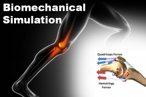
Flexible Body Analysis Using Vibration Modes

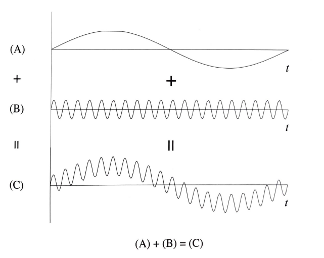
The finite element method, mentioned above, can be used to calculate the modal frequencies and mode shapes of a flexible body. The principle of superposition is used to combine individual mode shapes with weighting factors in order to reproduce any deformed shape of a flexible body. The weighting factors are also known as modal participation factors. This approach to representing flexible bodies has been offered in many dynamic simulation software for over 35 years.

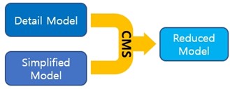
Component mode synthesis (CMS) is a substructuring method that uses mode shapes and frequencies to represent the structure. CMS was originally developed to solve complex structures in a reasonable time, when computers were much slower. With multibody dynamics we are solving the flexible body several times in each time step, so even though computers are much faster today we need fast techniques to do the millions of flexible body solves that may occur during a simulation.

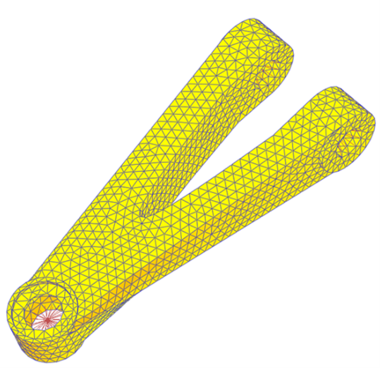
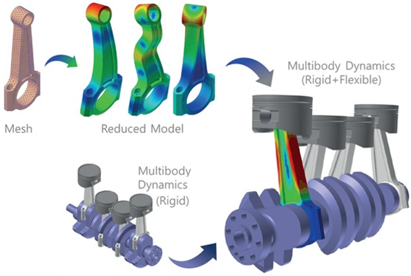
The use of the CMS flexible body in a multibody dynamics simulation requires the identification of attachment nodes in the finite element mesh. Some attachment nodes are located at joints/constraints and other attachment nodes are located where applied loads occur. Using finite elements software (including RFlexGen in RecurDyn) there are two sets of load cases that are investigated. First the attachment nodes at constraints are assumed to be fixed and a constrained normal modes analysis is run. Second, unit loads for each of the six degrees of freedom at each of the force attachment nodes are applied to create a set of constraint modes, which are also referred to as Craig-Bampton modes.

Advantages of Using Vibrational Modes for Flexible Body Analysis

Reduced computational complexity

CMS was developed for the reduction of finite element models and reduced computational time. For example, a detailed model, simplified model, and reduced model can all be created for the same flexible body in accordance with the degree of desired computational complexity. The starting finite element analysis model for CMS does not need to be as detailed as a model that is calculating the effect of geometric detail, such as stress concentrations. Second, the CMS model contains a small number of modes as compared to the number of finite element equations in the simplified models. In terms of computational complexity, a model with 100,000 nodes may have 300,000 equations to solve while the corresponding CMS model only has 100 equations to solve as related to the calculation of the modal participation factors as described above. Consequently, the use of flexible bodies using modes greatly reduces computational complexity, resulting in shorter computation times when arriving at solutions.

Reduction in effort needed to create flexible bodies

CMS
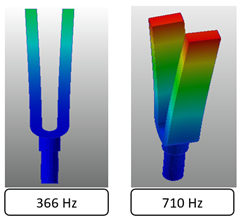
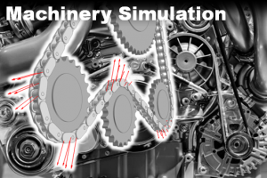
The meshes used in simplified models allow for sufficiently accurate results even if they are not as fine (small elements) as the meshes used for strength analyses (detailed model). If the subject is high frequency noise or acoustics, then a detailed model may be needed, but in general, the frequencies at issue for machinery are often in the 0 ~ 100Hz range. In such cases, creating and using a mesh that properly expresses rigidity and mass alone is not a problem. In particular, bending and torsion is extremely accurate for the low frequencies that are most often used in common machinery, so flexible bodies created by the reduction of simplified models through CMS can be used to solve machinery vibration issues.

Limitations of Using Vibration Modes for Flexible Body Analysis

Linear Behavior

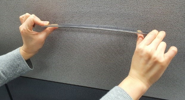
The deformation of a flexible body can be expressed as the combination of multiple mode shapes because of the principle of superposition, which only applies to linear systems. Simulation cases that are not linear systems include large overall deformations, hyper elastic materials such as rubber, and local plastic deformations. It is necessary to use RecurDyn FFlex in such cases where the flexible body behavior is nonlinear. Since generally there are small deformations involved when designing machines, most machine designs can be done with a linear analysis.

User Knowledge Required to Select Modes for MBD Simulation

The user selects the number of modes for the finite element analysis software to produce for the flexible body. In the RecurDyn multibody dynamics software the user has to decide which of the modes should be included in the model. If too many modes are included it can slow down the model run time. If too few modes are included, then the simulation results may be in error. Therefore, the user needs to make several runs initially in order to establish how many modes should be included for sufficient accuracy with a reasonable run time. This decision process is not needed when running FFlex.

Sliding and Rolling Contact

Much caution is needed when trying to include sliding or rolling contact with a modal flexible body. A contact applies a force to the body, but with sliding or rolling contact the force can’t be associated with a node because it is changing location. If the modal flexible body is quite stiff then it is possible to define such contacts if the treatment of the contact surface is carefully done.

Application of Modal Flexible Body Analysis

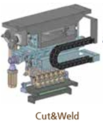
Flexible body analysis using vibrational modes can be used for many applications. This level of analysis is positioned between rigid body analysis that does not consider any body flexibility and complex, nonlinear flexible body analysis. A modal flexible body can produce useful results for system vibrations in the 100~200Hz range, such as might occur in the analyses of vehicle vibrations or passenger comfort. Other applications include automobiles, frames for operated machines such as construction equipment, frames for automated factory equipment, and other parts for machinery. The image portrays the simulation of an internal combustion engine with a flexible connecting rod.
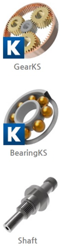
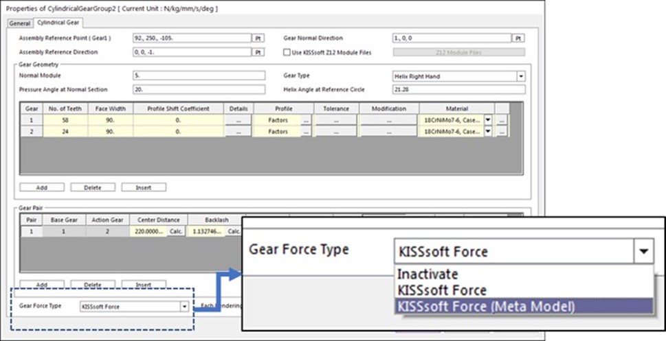
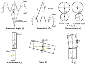
Modal Flexible Body Analysis