Using the Enhanced EHD (Elasto-Hydrodynamic Lubrication) Toolkits
Since the release of RecurDyn V9R1 an enhanced version of the EHD (Elasto-Hydrodynamic Lubrication) toolkit has been available to RecurDyn users. Now there are actually two EHD toolkits- the Rotational Lubrication toolkit and the Piston Lubrication toolkit. These toolkits enable RecurDyn to analyze the behavior of a lubricant film in the thin gap between rapidly-moving cylindrical surfaces and the hydrodynamic forces transmitted from the lubricant to the surfaces.The Rotational Lubrication toolkit is for modeling primarily rotational motion, such as the motion found in journal bearings. The Piston Lubrication toolkit is for modeling primarily translational motion. It also supports RFlex (Flexible) Body analysis.
EHD Overview
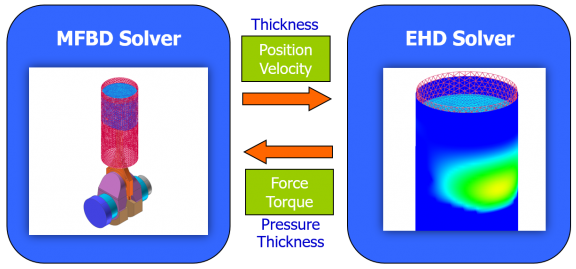
The goal of hydrodynamic lubrication is to have a lubricant that penetrates into the contact zone between rubbing solids and creates a thin liquid film. This film separates the surfaces from direct contact. In general, this reduces friction and can consequently reduce wear, since friction within the lubricant is less than between the directly contacting solids. The EHD toolkits consider viscosity and surface roughness and calculate the elastic hydrodynamic force as well as the asperity contact force. The EHD Force can be shown with a contour display and EHD results can be exported. The interactions between the mechanical model and the EHD solver is shown in the figure.
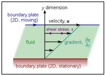
The history of lubrication theory goes back to 1886 when O. Reynolds published his famous equation of the fluid film flow in the narrow gap between two solids. The Reynolds equation carries his name and forms a foundation of the lubrication theory. The figure shows the consideration of shear stress in the fluid as a function of the relative velocity between the solid components.
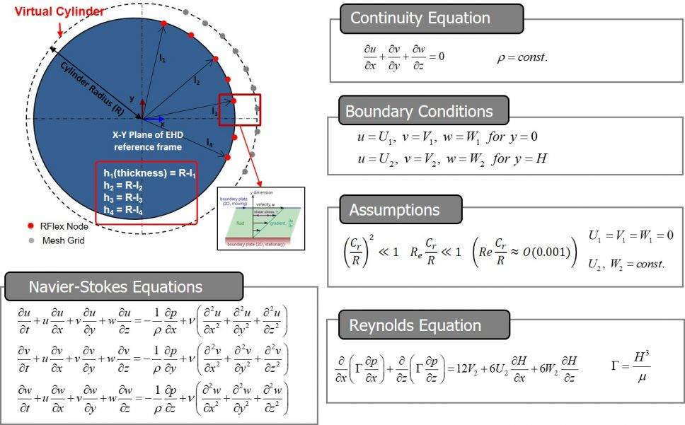
The calculation of the behavior of the local fluid lubrication region is determined by the governing equations in the figure.
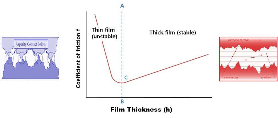
When considering the behavior of the lubrication region and the contact region there are two regimes of interest. A thin film is considered to have a height / roughness of less than 4 mm, and may have intermittent metal to metal contact. A thick film is considered to have a height / roughness of greater than 4 mm and the EHD lubrication should be stable. The figure graphically depicts these concepts.
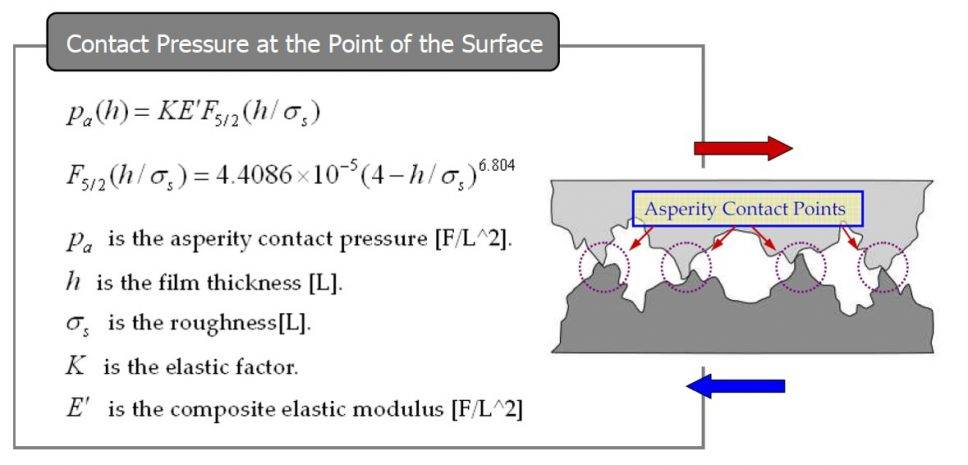
The governing equations for the contact region are given in the figure below.
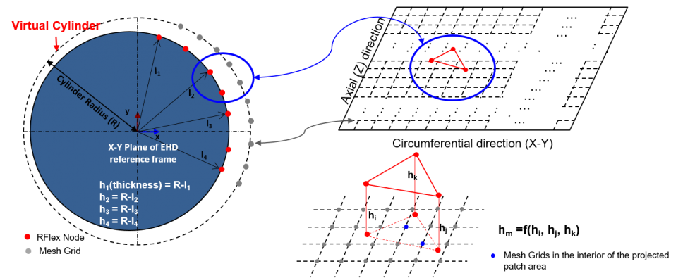
In the case of piston lubrication both the piston and the cylinder head are RFlex flexible bodies. The nodes in the piston mesh are mapped to nodes in the mesh grid of a virtual cylinder in order to detect interferences related to the contact modeling.
The EHD toolkits have their own license, so if you would like to use EHD Toolkit, please contact MotionPort to obtain a trial license. There is also a specific RecurDyn tutorial for the EHD toolkits, include pre-created example models:

