Category

Multibody Dynamics

Using the Enhanced EHD (Elasto-Hydrodynamic Lubrication) Toolkits

Using the Enhanced EHD (Elasto-Hydrodynamic Lubrication) Toolkits

Since the release of RecurDyn V9R1 an enhanced version of the EHD (Elasto-Hydrodynamic Lubrication) toolkit has been available to RecurDyn users. Now there are actually two EHD toolkits- the Rotational Lubrication toolkit and the Piston Lubrication toolkit. These toolkits enable RecurDyn to analyze the behavior of a lubricant film in the thin gap between rapidly-moving cylindrical surfaces and the hydrodynamic forces transmitted from the lubricant to the surfaces.The Rotational Lubrication toolkit is for modeling primarily rotational motion, such as the motion found in journal bearings. The Piston Lubrication toolkit is for modeling primarily translational motion. It also supports RFlex (Flexible) Body analysis.

EHD Overview

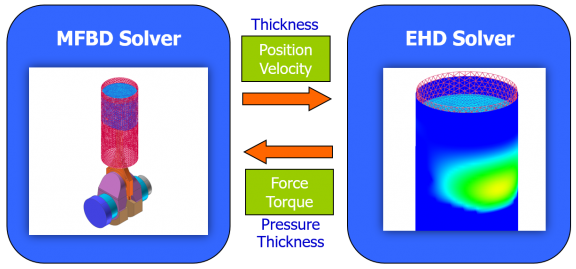
The goal of hydrodynamic lubrication is to have a lubricant that penetrates into the contact zone between rubbing solids and creates a thin liquid film. This film separates the surfaces from direct contact. In general, this reduces friction and can consequently reduce wear, since friction within the lubricant is less than between the directly contacting solids. The EHD toolkits consider viscosity and surface roughness and calculate the elastic hydrodynamic force as well as the asperity contact force. The EHD Force can be shown with a contour display and EHD results can be exported. The interactions between the mechanical model and the EHD solver is shown in the figure.

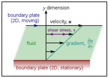
The history of lubrication theory goes back to 1886 when O. Reynolds published his famous equation of the fluid film flow in the narrow gap between two solids. The Reynolds equation carries his name and forms a foundation of the lubrication theory. The figure shows the consideration of shear stress in the fluid as a function of the relative velocity between the solid components.

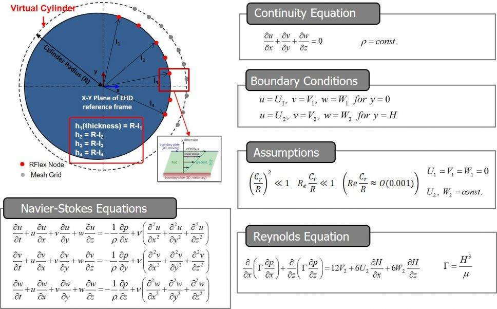
The calculation of the behavior of the local fluid lubrication region is determined by the governing equations in the figure.

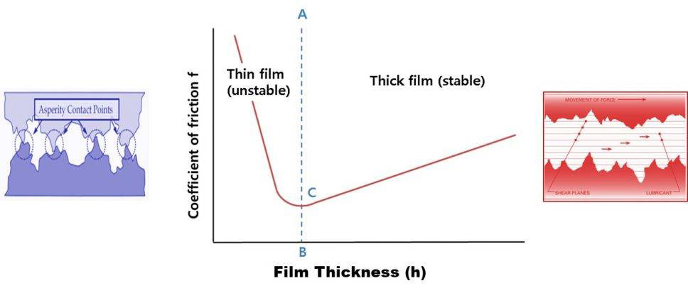
When considering the behavior of the lubrication region and the contact region there are two regimes of interest. A thin film is considered to have a height / roughness of less than 4 mm, and may have intermittent metal to metal contact. A thick film is considered to have a height / roughness of greater than 4 mm and the EHD lubrication should be stable. The figure graphically depicts these concepts.

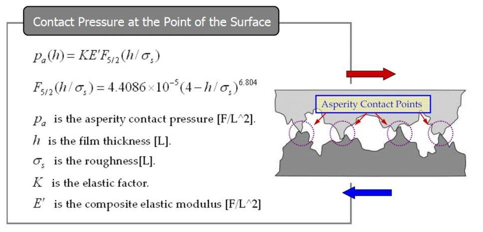
The governing equations for the contact region are given in the figure below.

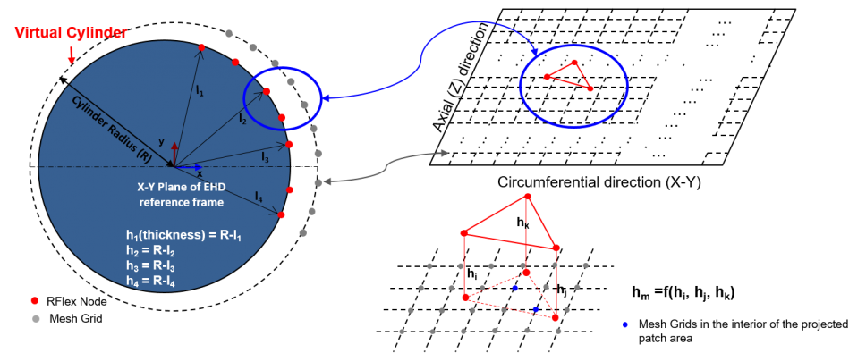
In the case of piston lubrication both the piston and the cylinder head are RFlex flexible bodies. The nodes in the piston mesh are mapped to nodes in the mesh grid of a virtual cylinder in order to detect interferences related to the contact modeling.

The EHD toolkits have their own license, so if you would like to use EHD Toolkit, please contact MotionPort to obtain a trial license. There is also a specific RecurDyn tutorial for the EHD toolkits, include pre-created example models:

Tips for mesh generation – Using the Gradation Factor and Chordal Error Ratio Parameters to Control the Mesh Density

Tips for mesh generation – Using the Gradation Factor and Chordal Error Ratio Parameters to Control the Mesh Density

When you mesh complex geometry, you can improve the simulation speed and accuracy by generating a non-uniform mesh, with varying mesh density. The guiding concept is that a higher mesh density should be used in regions of high stress (and high stress gradients) while a lower mesh density can be used in area of low stress (and low stress gradients).

Note: ‘Mesh density’ is defined as the number of elements per unit distance in a mesh. A high mesh density generally produces more accurate results while a low mesh density can be simulated faster.

The RecurDyn/Mesher provides several options to generate a variable mesh efficiently. This article introduces two important parameters, the Gradation Factor and the Chordal Error Ratio. These parameters, when used properly, cause the mesh to have the proper mesh densities at curved surfaces or small features.

The definitions of the two parameters are as follows (please also refer to the images):

  • Chordal Error Ratio: It is the error between ideal curve (arc) and the approximated mesh as compared to the segment length. A smaller value produces a denser mesh on curved geometry that is more accurate.
  • Gradation Factor: It defines the rate at which the mesh transitions between high mesh density and low mesh density. The default value is 2. If you use a smaller value, the element size will vary more slowly.

A comparison of the images in the top half of the figure above shows that the reduction of the Chordal Error Ratio by a factor of 10 results in high mesh density along all of the arcs along the perimeter of the Geneva wheel as well as the circle in the center. Then, looking at the images in the bottom half of the figure shows that an 80% reduction of the Gradation Factor results in a much slower transition from a high-density mesh to a low-density mesh.

The best practice is to adjust these two parameters such that the transition in mesh density matches the transition of strain energy in the structure, while keeping the total number of nodes and elements low enough to allow for reasonable simulation times.

RecurDyn V9R2 capability to include FFlex bodies in co-simulations with Particleworks

RecurDyn V9R2 capability to include FFlex bodies in co-simulations with Particleworks

In earlier versions of RecurDyn and Particleworks the fluid particles could only interact with rigid bodies. Now, RecurDyn V9R2 has the capability to include FFlex bodies in co-simulations with Particleworks. An interesting tutorial uses the example of a styler steam clothing care system to teaches how to perform a co-simulation between RecurDyn and Particleworks. The co-simulation illustrates the dynamic interaction between the shaking mechanism and the flexible bodies (representing the clothes) in RecurDyn and the fluid particles of Particleworks that represent the steam.

The styler unit, shown in the image, is used to shake off the dust attached to cloth and to remove its wrinkles with steam. It also reduces the odors and allergens in the clothing.

The tutorial analyzes the dynamic interaction between an item of clothing, which is expressed as a flexible body, and the steam, which is expressed as particles.

After the co-simulation, an analysis is made of the stress in the clothing as the particles touch the flexible body, using the Contour function of RecurDyn.

To learn more about the styler unit, perform a search on your favorite search engine using the text: “styler steam clothing care system.”

The Styler co-simulation video covers the following topics (with time stamps): Creating walls (0:30), Exporting walls (1:55), Creating steam particles (2:16), Setting fluid properties (3:26), Co-simulation (7:32), Post-processing (8:45)

Click play below to watch the video (approx. 9:38).

More examples of RecurDyn and Particleworks co-simulation in action:

RecurDyn and Particleworks co-simulation: Washing machine

Concept for a self-correcting sheet metal bending operation

Concept for a self-correcting sheet metal bending operation

U. Damerow, D. Tabakajew, M. Borzykh, W. Schaermann, W. Homberg, A. Trachtler, Procedia Technology, 2014, Volume 15, pp 439-446.

Abstract

Geometrical deviations can appear in the production of plug contacts used in electrical connection technology and in fittings for the furniture industry. The reasons for this can be a variation in the properties of the semi-finished product, or wear phenomena on the forming machine itself or on the bending tools. When geometrical deviations appear, the process parameters normally have to be adjusted manually. Finding the most appropriate process parameters is currently done manually and is thus very time consuming. In order to reduce the scrap rate and the setup time for production scenarios, a concept for self-correcting bending operations is being developed using the V-model of the VDI guideline 2206. In this case, the V-model will make it possible to set up a self-correcting control strategy consisting of a closed-loop control approach, measurement devices and actuators. Having implemented these components in the forming machines, it will be possible to recognize geometrical deviations automatically and to take corrective action during production, aiming at a reduction of the scrap rate and setup-time.

How Multibody Dynamics Simulation Technology is Used

RecurDyn was used to simulate sheet metal bending operations. A RecurDyn model has a major advantage over traditional FEA models when it comes to designing a control strategy for bending operations. RecurDyn simulations can determine what corrective actions need to be taken when geometrical deviations appear.

Get This Paper

Related Case Studies

Surface Modification and Software Design of Customized Knee Joint

Surface Modification and Software Design of Customized Knee Joint

Chin YU Wang, Chien Fen Huang, Yi-Lin Liou, Life Science Journal, December 2014, Volume 11, Number 12, Article 137.

Abstract

This paper used the medical image of a patient’s knee joint as basis to assemble a complete human knee through geometric software. Because this model can’t precisely align the position, local contact will occur which would cause stress concentration. It should undergo the tension adjustment of the ligaments to adjust the relative positions of the cartilage of the femoral condyle, the meniscus and the femoral cartilage to the minimal relative position of the contact stress to comply with the lowest energy or stress allowed by the law of nature for our body needs. First, this study used the spring simulation in the ligament tension and used the software, RecurDyn, to find the relative position of the minimum contact stress of the knee system. Second, the customized man-made knee was imported in the biomechanical software called LifeMod to build muscles and the ligaments system to simulate the ligament tensions of the artificial knee under a variety of sports. Aside from being the basis for the spring coefficient setting of the human knee, the tension can also select the specific posture of the knee in the model and then convert it into a file of ANSYS stress analysis software to complete a more accurate stress analysis. Finally, we can retest the human and artificial knee joints under different postures in the above steps to know the changes in the patterns between contact stress and contact area to obtain customized artificial knee prosthesis closest to the patient’s original human knee joints. The concept is the same if the original denture tooth shape is kept, we can be able to organize the most stable and compatible peripherals, prolong the life of the prosthesis and reduce its possibility of loosening.

How Multibody Dynamics Simulation Technology is Used

RecurDyn is used to perform dynamic simulation of an artificial knee. The geometry of the artificial knee is imported into RecurDyn from a CAD program. Accurate data from physical testing can be limited and difficult to obtain. RecurDyn provides an easy way to test if design parameters are within an acceptable performance range.

Get This Paper

Related Case Studies

Compensation of geometrical deviations via model based-observers

Compensation of geometrical deviations via model based-observers

B.Denkena, L.Overmeyer, K.M.Litwinski, R.Pesters, 2014, The International Journal of Advanced Manufacturing Technology, July 2014, Volume 73, Issue 5, pp 989-998.

Influence of Bundle Diameter and Attachment Point on Kinematic Behavior in Double Bundle Anterior Cruciate Ligament Reconstruction Using Computational Model

Influence of Bundle Diameter and Attachment Point on Kinematic Behavior in Double Bundle Anterior Cruciate Ligament Reconstruction Using Computational Model

Oh Soo Kwon, Tserenchimed Purevsuren, Kyungsoo Kim, Won Man Park, Tae-Kyu Kwon, Yoon Hyuk Kim, Computational and Mathematical Methods in Medicine, January 2014, Volume 2014, Article ID 948292, 8 pages.

  • Abstract

    A protocol to choose the graft diameter attachment point of each bundle has not yet been determined since they are usually dependent on a surgeon’s preference. Therefore, the influence of bundle diameters and attachment points on the kinematics of the knee joint needs to be quantitatively analyzed. A three-dimensional knee model was reconstructed with computed tomography images of a 26-year-old man. Based on the model, models of double bundle anterior cruciate ligament (ACL) reconstruction were developed. The anterior tibial translations for the anterior drawer test and the internal tibial rotation for the pivot shift test were investigated according to variation of bundle diameters and attachment points. For the model in this study, the knee kinematics after the double bundle ACL reconstruction were dependent on the attachment point and not much influenced by the bundle diameter although larger sized anterior-medial bundles provided increased stability in the knee joint. Therefore, in the clinical setting, the bundle attachment point needs to be considered prior to the bundle diameter, and the current selection method of graft diameters for both bundles appears justified.

    How Multibody Dynamics Simulation Technology is Used

    RecurDyn provides nonlinear force entities to model tissues such as ligaments, as well as contact modeling capabilities needed to simulate the movement of ligaments around bone and cartilage boundaries.

    Get This Paper

    Related Case Studies

A method for reducing the energy consumption of pick and place industrial robots

A method for reducing the energy consumption of pick and place industrial robots

M. Pellicciari, G. Berselli, F. Leali, A. Vergnano, Mechatronics, April 2013, Volume 23, Issue 3, pp. 326-334.