Category

Machinery General

Using the Enhanced EHD (Elasto-Hydrodynamic Lubrication) Toolkits

Using the Enhanced EHD (Elasto-Hydrodynamic Lubrication) Toolkits

Since the release of RecurDyn V9R1 an enhanced version of the EHD (Elasto-Hydrodynamic Lubrication) toolkit has been available to RecurDyn users. Now there are actually two EHD toolkits- the Rotational Lubrication toolkit and the Piston Lubrication toolkit. These toolkits enable RecurDyn to analyze the behavior of a lubricant film in the thin gap between rapidly-moving cylindrical surfaces and the hydrodynamic forces transmitted from the lubricant to the surfaces.The Rotational Lubrication toolkit is for modeling primarily rotational motion, such as the motion found in journal bearings. The Piston Lubrication toolkit is for modeling primarily translational motion. It also supports RFlex (Flexible) Body analysis.

EHD Overview

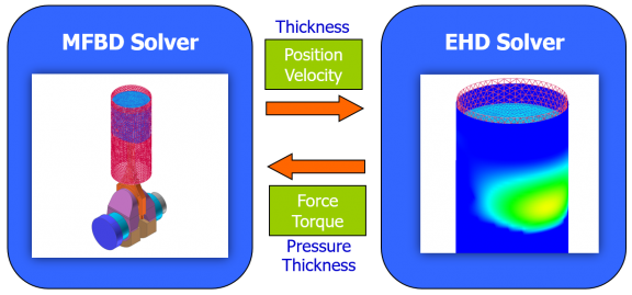
The goal of hydrodynamic lubrication is to have a lubricant that penetrates into the contact zone between rubbing solids and creates a thin liquid film. This film separates the surfaces from direct contact. In general, this reduces friction and can consequently reduce wear, since friction within the lubricant is less than between the directly contacting solids. The EHD toolkits consider viscosity and surface roughness and calculate the elastic hydrodynamic force as well as the asperity contact force. The EHD Force can be shown with a contour display and EHD results can be exported. The interactions between the mechanical model and the EHD solver is shown in the figure.
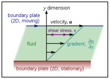
The history of lubrication theory goes back to 1886 when O. Reynolds published his famous equation of the fluid film flow in the narrow gap between two solids. The Reynolds equation carries his name and forms a foundation of the lubrication theory. The figure shows the consideration of shear stress in the fluid as a function of the relative velocity between the solid components.

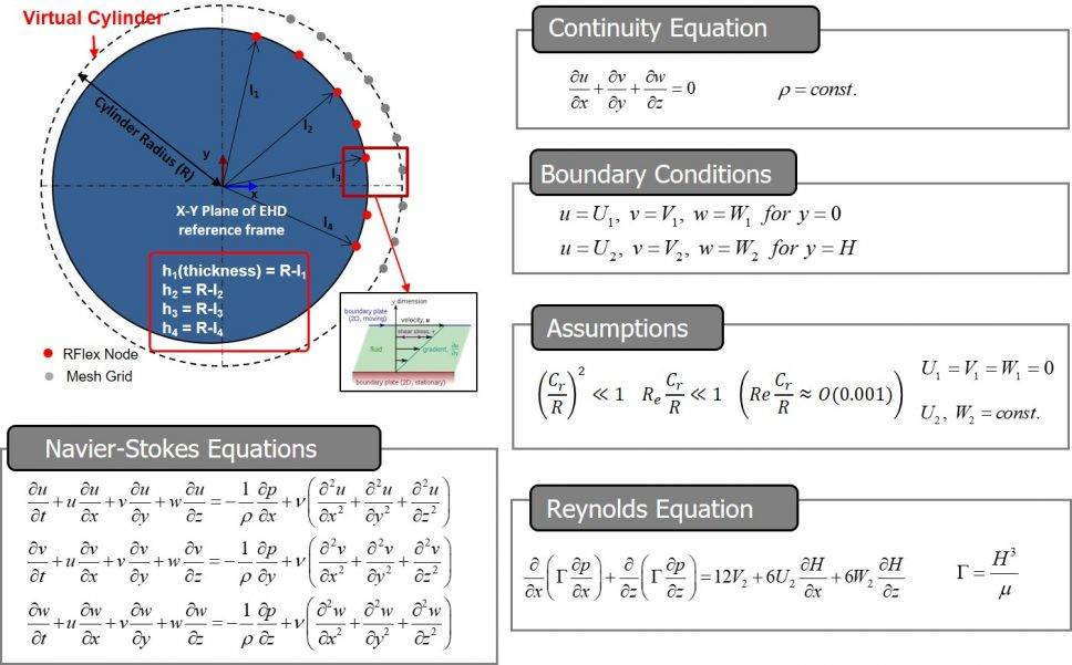
The calculation of the behavior of the local fluid lubrication region is determined by the governing equations in the figure.
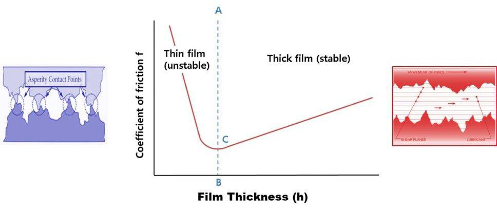
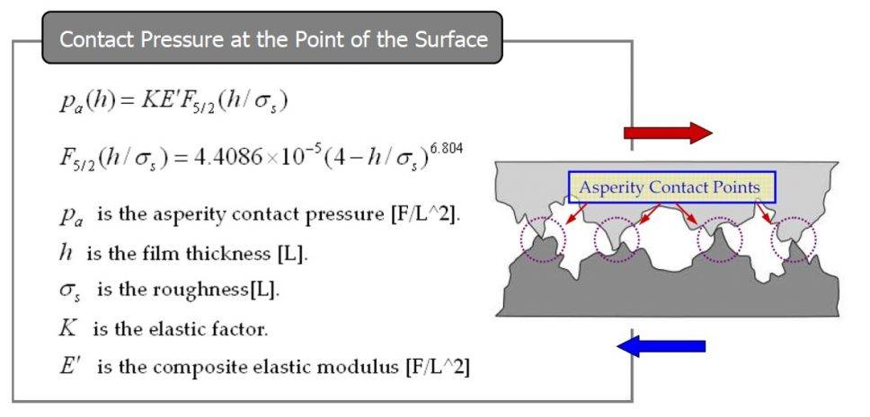
When considering the behavior of the lubrication region and the contact region there are two regimes of interest. A thin film is considered to have a height / roughness of less than 4 mm, and may have intermittent metal to metal contact. A thick film is considered to have a height / roughness of greater than 4 mm and the EHD lubrication should be stable. The figure graphically depicts these concepts.
The governing equations for the contact region are given in the figure below.
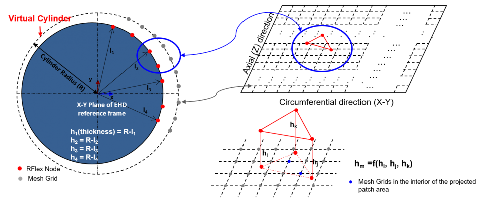
In the case of piston lubrication both the piston and the cylinder head are RFlex flexible bodies. The nodes in the piston mesh are mapped to nodes in the mesh grid of a virtual cylinder in order to detect interferences related to the contact modeling.
The EHD toolkits have their own license, so if you would like to use EHD Toolkit, please contact MotionPort to obtain a trial license. There is also a specific RecurDyn tutorial for the EHD toolkits, include pre-created example models:

RecurDyn V9R2 capability to include FFlex bodies in co-simulations with Particleworks

RecurDyn V9R2 capability to include FFlex bodies in co-simulations with Particleworks

In earlier versions of RecurDyn and Particleworks the fluid particles could only interact with rigid bodies. Now, RecurDyn V9R2 has the capability to include FFlex bodies in co-simulations with Particleworks. An interesting tutorial uses the example of a styler steam clothing care system to teaches how to perform a co-simulation between RecurDyn and Particleworks. The co-simulation illustrates the dynamic interaction between the shaking mechanism and the flexible bodies (representing the clothes) in RecurDyn and the fluid particles of Particleworks that represent the steam.

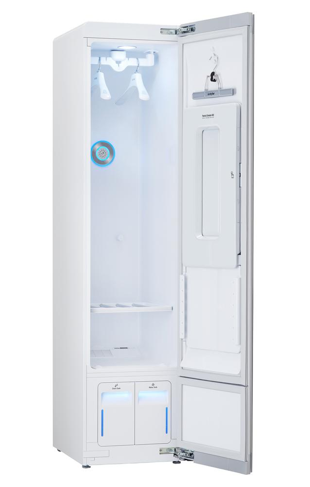
The styler unit, shown in the image, is used to shake off the dust attached to cloth and to remove its wrinkles with steam. It also reduces the odors and allergens in the clothing.

The tutorial analyzes the dynamic interaction between an item of clothing, which is expressed as a flexible body, and the steam, which is expressed as particles.

After the co-simulation, an analysis is made of the stress in the clothing as the particles touch the flexible body, using the Contour function of RecurDyn.

To learn more about the styler unit, perform a search on your favorite search engine using the text: “styler steam clothing care system.”

The Styler co-simulation video covers the following topics (with time stamps): Creating walls (0:30), Exporting walls (1:55), Creating steam particles (2:16), Setting fluid properties (3:26), Co-simulation (7:32), Post-processing (8:45)

Click play below to watch the video (approx. 9:38).

More examples of RecurDyn and Particleworks co-simulation in action:

RecurDyn and Particleworks co-simulation: Washing machine

Design of planar static balancer with associated linkage

Design of planar static balancer with associated linkage

Sang-Hyung Kim, Chang-Hyun Cho, Mechanism and Machine Theory, November 2014, Volume 81, pp 79-93.

Abstract

This paper presents a design method for a static balancer with associated linkage. Various mechanisms can be obtained with modifications to the associated linkage. Gravity compensators for various mechanisms can be achieved similarly from a gravity compensator for the associated linkage. The space mapping method is adopted to design a gravity compensator for the associated linkage. Conversion rules are derived by investigating the variances of a mechanism from the associated linkage and are applied to the design equation for the associated linkage generated by the space mapping method. Rows and columns of the design equation are deleted by conversion rules, leading to deletion rules. A new gravity compensator for the mechanism derived from the associated linkage is obtained by applying the deletion rules to the design equation (i.e., gravity compensator) for the associated linkage. The four-bar mechanism is adopted as the associated linkage, and various gravity compensators for planar mechanisms are derived from the gravity compensator of the four-bar linkage. Simulations are conducted, and the results show that complete gravity compensation is possible for various planar mechanisms.This paper is mainly about quadruped robot gait planning with stair environment constraints, where the environment constraints are mainly embodied in the form of robot gait planning constraints and robot stair traversing feasibility, etc., and the problem of quadruped robot gait planning can be solved theoretically with Stair-Aimed-SSG (Static Stable Gait). The feasibility of this scheme is proved by Matlab and RecurDyn simulation. This paper is mainly about quadruped robot gait planning with stair environment constraints, where the environment constraints are mainly embodied in the form of robot gait planning constraints and robot stair traversing feasibility, etc., and the problem of quadruped robot gait planning can be solved theoretically with Stair-Aimed-SSG (Static Stable Gait). The feasibility of this scheme is proved by Matlab and RecurDyn simulation.

How Multibody Dynamics Simulation Technology is Used

RecurDyn was used for dynamic simulations of gravity compensators. Several designs could be tested quickly to fine tune the design without having to build many physical prototypes.

Get This Paper

Related Case Studies

Changing law of launching pitching angular velocity of rotating missile

Changing law of launching pitching angular velocity of rotating missile

Guang Liu, Bin Xu, Xiaojuan Jiao, Tiesheng Zhen, Chinese Journal of Aeronautics, October 2014, Volume 27, Issue 5, pp 1171-1179.

Abstract

In order to provide accurate launching pitching angular velocity (LPAV) for the exterior trajectory optimization design, multi-flexible body dynamics (MFBD) technology is presented to study the changing law of LPAV of the rotating missile based on spiral guideway. An MFBD virtual prototype model of the rotating missile launching system is built using multi-body dynamics modeling technology based on the built flexible body models of key components and the special force model. The built model is verified with the frequency spectrum analysis. With the flexible body contact theory and nonlinear theory of MFBD technology, the research is conducted on the influence of a series of factors on LPAV, such as launching angle change, clearance between launching canister and missile, thrust change, thrust eccentricity and mass eccentricity, etc. Through this research, some useful values of the key design parameters which are difficult to be measured in physical tests are obtained. Finally, a simplified mathematical model of the changing law of LPAV is presented through fitting virtual test results using the linear regression method and verified by physical flight tests. The research results have important significance for the exterior trajectory optimization design.In this paper we describe the necessity and significance of coal preparation plant inspection robot, propose the robot design requirements and design the system framework of hardware and software. Then we use RecurDyn software to simulate and analysis the stability and fitness of the inspection robot in coal preparation plant complex environment based on virtual prototype technique.

How Multibody Dynamics Simulation Technology is Used

A multi-flexible body dynamics (MFBD) virtual prototype of a missile launching system is simulated using the RecurDyn FFlex module. A meshed model of the missile and the launching canister were imported into RecurDyn to perform dynamic analysis. The stress profile of the missile and launching canister were obtained where instrumentation for physical testing would be difficult.

Get This Paper

Related Case Studies

Modeling and dynamics analysis of helical spring under compression using a curved beam element with consideration on contact between its coils

Modeling and dynamics analysis of helical spring under compression using a curved beam element with consideration on contact between its coils

C.J. Yang, W.H. Zhang, G.X. Ren, X.Y. Lin, Meccanica, April 2014, Volume 49, Issue 4, pp 907-917.

Abstract

Helical springs are indispensable elements in mechanical engineering. This paper investigates helical springs subjected to axial loads under different dynamic conditions. The mechanical system, composed of a helical spring and two blocks, is considered and analyzed. Multibody system dynamics theory is applied to model the system, where the spring is modeled by Euler–Bernoulli curved beam elements based on an absolute nodal coordinate formulation. Compared with previous studies, contact between the coils of spring is considered here. A three-dimensional beam-to-beam contact model is presented to describe the interaction between the spring coils. Numerical analysis provides details such as spring stiffness, static and dynamic stress for helical spring under compression. All these results are available in design of helical springs.

How Multibody Dynamics Simulation Technology is Used

RecurDyn simulations were used to validate a simplified contact model between coils of a spring. The spring was modeled using beam elements and important information for the design of helical springs such as spring stiffness, static and dynamic stress are compared with RecurDyn simulations. The result is that the simplified method is proven to be effective.

Get This Paper

Related Case Studies

Necessary conditions of stability moving parts of rotor centrifuge

Necessary conditions of stability moving parts of rotor centrifuge

Jens Strackeljan, Andriy Babenko, Iaroslav Lavrenko, Journal of Mechanical Engineering, 2014, Number 72.

Abstract

Considered design features modern centrifuges. Revealed that their rotors have moving parts that rotate around a horizontal axis. The dynamics of said moving elements. Using Lagrange equation of the second kind derived differential equations of motion. The simulation visualization of motion using the software package RecurDyn. The research results obtained with the package RecurDyn and analytically showed that their movement can not be sustained, in the positions that are optimal in terms of process. The resulting differential equations can not be prointehrovani elementary functions, so direct traffic analysis difficult. Due to the foregoing stability conditions investigated linear movement approach. Necessary conditions for stability of motion required of the design.

How Multibody Dynamics Simulation Technology is Used

A dynamic model of a modern centrifuge with moving parts that rotate around a horizontal axis. The goal of this design was to have a high centrifugal force while maintaining motion stability. RecurDyn simulations showed that the motion was unstable in positions that were optimal for the technological process. The results showed that the design needs to be adjusted to provide additional stability.

Get This Paper

Related Case Studies

A Numerical Method of Large-Scale Concrete Displacing Boom Dynamics and Experimental Validation

A Numerical Method of Large-Scale Concrete Displacing Boom Dynamics and Experimental Validation

Wu Ren, Yun-xin Wu, Zhao-wei Zhang, Wen-ze Shi, Advances in Mechanical Engineering, January 2014, Volume 6 943847.

Abstract

Concrete displacing boom is large-scale motion manipulator. During the long distance pouring the postures needs to frequently change. This makes the real-time dynamic analysis and health monitoring difficult. Virtual spring-damper method is adopted to establish the equivalent hydraulic actuator model. Besides boom cylinder joint clearance is taken into account. Then transfer matrix method is used to build the multibody concrete placing boom model by dividing the system into two substructures. Next typical working conditions displacements and accelerations during the pouring process are studied. The results of the numerical method are correct and feasible compared with RecurDyn software and the experimental ones. So it provides reference to the real-time monitoring and structure design for such light weight large scale motion manipulators.

How Multibody Dynamics Simulation Technology is Used

A numerical method for concrete-displacing boom dynamics is developed and found to be in good agreement with RecurDyn and experimental results. RecurDyn simulations offer validity to the numerical and experimental methods while providing additional information that may not be available with instrumentation.

Get This Paper

Related Case Studies

Quantitative diagnosis of a spall-like fault of a rolling element bearing by empirical mode decomposition and the approximate entropy method

Quantitative diagnosis of a spall-like fault of a rolling element bearing by empirical mode decomposition and the approximate entropy method

ShuanFeng Zhao, Lin Liang, GuangHua Xu, Jing Wang, WenMing Zhang, Mechanical Systems and Signal Processing, October 2013, Volume 40, Issue 1, pp 154-177.

Abstract

Spalling or pitting is the main manifestation of fault development in a bearing during the earlier stages. Previous studies indicated that the vibration signal of a bearing with a spall-like defect may be composed of two parts; the first part originates from the entry of the rolling element into the spall-like area, and the second part refers to the exit from the fault region. The quantitative diagnosis of a spall-like fault of the rolling element bearing can be realized if the entry–exit event times can be accurately calculated. However, the vibration signal of a faulty bearing is usually non-stationary and non-linear with strong background noise interference. Meanwhile, the signal energy from the early spall region is too low to accurately register the features of the entry–exit event in the time domain. In this work, the approximate entropy (ApEn) method and empirical mode decomposition (EMD) are applied to clearly separate the entry–exit events, and thus the size of the spall-like fault is estimated.

How Multibody Dynamics Simulation Technology is Used

RecurDyn is used to simulate the dynamic effects of rolling element bearings with spall-like faults. A variety of spall widths and bearing speeds were tested without the cost and time associated with physical prototypes.

Get This Paper

Related Case Studies

Auto-positioning of sliding planes based on virtual force

Auto-positioning of sliding planes based on virtual force

Eun Ho Kim, Kyung Woon Kwak, Young Kook Kim, Soohyun Kim, Byung Man Kwak, In Gwun Jang, Kyung Soo Kim, International Journal of Control, Automation and Systems, August 2013, Volume 11, Issue 4, pp 798-804.

Abstract

In this paper, an auto-positioning algorithm for sliding planes is newly proposed in two different forms: the General Virtual Force Algorithm (GVFA) and the Applied Virtual Force Algorithm (AVFA). The proposed algorithm is then applied to an auto-positioning spreader which can slide on the top surface of a container with 3 degrees of freedom (DOF). This enables the spreader to handle containers even on a wavy open sea, where the inevitable swinging motion of a spreader leads to significant misalignment from the container during landing. With numerical simulation and experiments using a 1/20 scale model, it is verified that the proposed algorithms provide a robust and reliable solution for in-plane path-finding. Considering the limited space and cost for sensor equipment, however, using AVFA with 8 sensors can be a better solution for an actual application regardless of the slight sacrifice in performance in terms of operation time and energy consumed.

How Multibody Dynamics Simulation Technology is Used

A newly proposed auto-positioning algorithm for sliding planes was tested using RecurDyn and scale testing. Scale testing was able to validate the RecurDyn model. RecurDyn simulations were able to prove that the algorithms provide a robust and reliable solution for path finding.

Get This Paper

Related Case Studies

Dynamic Analysis of Needle Roller Bearings on Torque Loss

Dynamic Analysis of Needle Roller Bearings on Torque Loss

Atsushi Suzuki, Hideki Sugiura, Miki Mizono, Mizuho Inagaki, Tsune Kobayashi, Journal of System Design and Dynamics, 2013, Volume 7, No. 4, pp 405-415.

Abstract

Automatic transmissions consist of several planetary gear sets that are utilized to change gears. Needle roller bearings are widely employed in planetary gears used under high-load and high-speed conditions, and thus the torque loss of these bearings is an important issue in designing high-efficiency transmissions. In this paper, a dynamic analysis is conducted using a multibody dynamics model to investigate friction losses in the needle roller bearings that support pinions. This numerical model takes into consideration the detailed conditions of contact and friction between the needle rollers and other parts. A discrete sphere model is used in the contact analysis to simulate the load distribution for the needle rollers. The friction coefficient is defined as a function of sliding velocity, and is used to describe the experimentally determined relationship between the skew angle and thrust force of needle rollers. The measurements obtained for the axial force of a pinion validate the predictions of the numerical model. A numerical analysis is conducted to evaluate the radial and cage pocket clearances of needle roller bearings, and it is found that the cage pocket clearance is a dominant factor affecting the friction loss of pinion. An increase in loss is caused by the thrust force generated by the skew of the needle rollers. Consequently, the cage pocket clearance needs to be small so as to lessen the friction loss of the bearing.

How Multibody Dynamics Simulation Technology is Used

RecurDyn is used to analyze the design of needle roller bearings in the planetary gears of an automatic transmission. Dynamic analysis in RecurDyn yielded the mechanisms of skew motion, the thrust force of the needle rollers, the axial force of the pinion and the friction torque. As a result, the design could be changed to reduce torque loss in the needle roller bearings.

Get This Paper

Related Case Studies